Modelling a building using 'Blender' software
We shall model historic buildings in 3D, starting from documents.
Chiswick House
|
Historical note : We shall start with Chiswick House, a house in Palladian style designed in 1725 by the Earl of Burlington (1694-1753) to the West of London
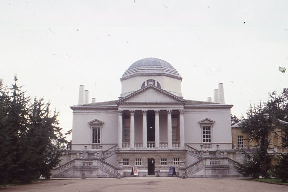
Project : · Such buildings, named after the Italian Renaissance architect Palladio, consisted of geometrical volumes with mathematical proportions ; see the RIBA (Royal Institute of British Architects) pages showing the elevation and plan of Palladian villas, notably the Villa Rotonda in Vicenza (near Venice) which served as a model for Chiswick . · It will be a starting point to learn the basis of computer modelling: creating geometrical volumes. As a guide, we shall use a present-day photo of the front of the house and the plan published in 1727 by an architect who worked under Burlington, William Kent. |
 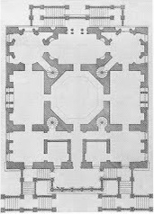 |
|
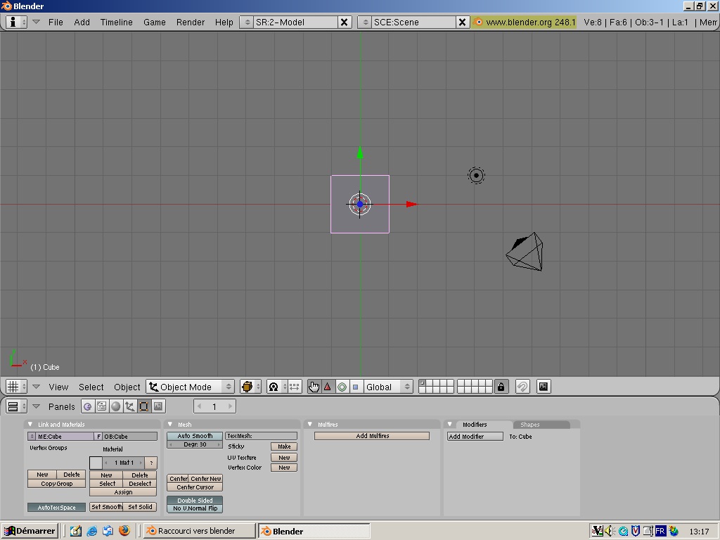
We shall use Blender (an open-source 3D modelling programme you may download at http://www.blender.org). The Blender interface - (in addition to the main grey window, you will see a small black window, never close it as this would close your work): · Menus on top, such as 'File' with Save option as usual · the main part, the 3D view with a grid, where we shall create volumes o it has three main variants marked by perpendicular arrows in the lower left corner, between which you can switch using the 'View' menu below § top view, the default view when you open Blender, marked by a red arrow (x, lateral direction) and a green one (y, depth) § front view, marked by the red arrow (x, lateral direction) and a blue one (z, height) § side view, marked
by the green arrow (y, depth) and the blue one (z, height) o the 3D window contains 3 elements by default: § a cube, which we shall retain and use as a starting point for the house § a lamp (the circle with dots)- you may change its position to throw light on a different wall or to change the direction of the shadows § a camera- the perspective view being taken from the camera, which you may also reposition to have a render from another point of view. Press F12 to view the model as the user will see it. · the Header, a bar containing both menus ('View') and buttons ('Manipulator'- the blue square) · the Buttons panels with numerous options that we shall explore
|
|
|
The house: Scale: We are in top view. The house is built on a square plan with a side of 68 feet, which we shall use to scale the volume: select the cube with a right click of the mouse (in Blender, right click for selection), press the S key for scaling, and drag the dotted line backwards till each side of the cube covers 6,8 units (6 squares of the grid – 3 on each side of the middle - plus slightly less than half a square -0,4- at both ends). |
|
|
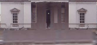
Texture : · we shall now add an image of the front of the house to one face of the cube (in very accurate modelling, we should have to imitate the projecting mouldings and the window sills, but for our first attempt we shall only model the major volumes - central block, portico and dome-, so we use this image of the wall including the windows, with the projecting parts of the portico suppressed so that we model them afterwards). Save the image opposite (right-click then ‘Save image’ in a new folder of your choice on your hard disk, where you will keep your material for the project). · Keeping the volume selected (pink outline- right-click to select a volume), in the buttons panel, click on the ‘materials’ button (the grey ball) which opens the materials panel, with the 'red ball' button, click on it to give a material to your volume. Then click on the texture button (the one like a leopard skin next to it) ; we shall not give our volume a preordained texture (wood, marble... as they appear in the menu) but an texture imported from our photos; so in the list of 'texture types' (click ‘add new’ if necessary) select the 'texture type' named ‘image,’ then click on the ‘load’ button which appears and browse for the image you have saved, by moving the arrows on the top left of the screen which appears, then click 'Select image'; you will have a preview in the lower left corner. · To view the result , press F12. You will see the façade is not well positioned, it is on the top (you may move the camera to view it better), so return to the 3D view, select the volume and after selecting the view (side or front) which will give the correct rotation, press R (rotate) and turn the volume on itself with the mouse, then do F12 again to check the result. · Once the façade is on one the vertical sides, you will see that the proportions are wrong: the plan of the house is a square so we shall keep the dimensions in the horizontal plane, but in the elevation the height should be half the length, not equal to it. In the 3D view, take a front view of the façade, and in the header select the ‘manipulator’ (the blue square) and pull down the blue vertical line from its square tip till the height becomes 3,4 units of the grid. Do F12 to check the result (We model just one side) |
|
|
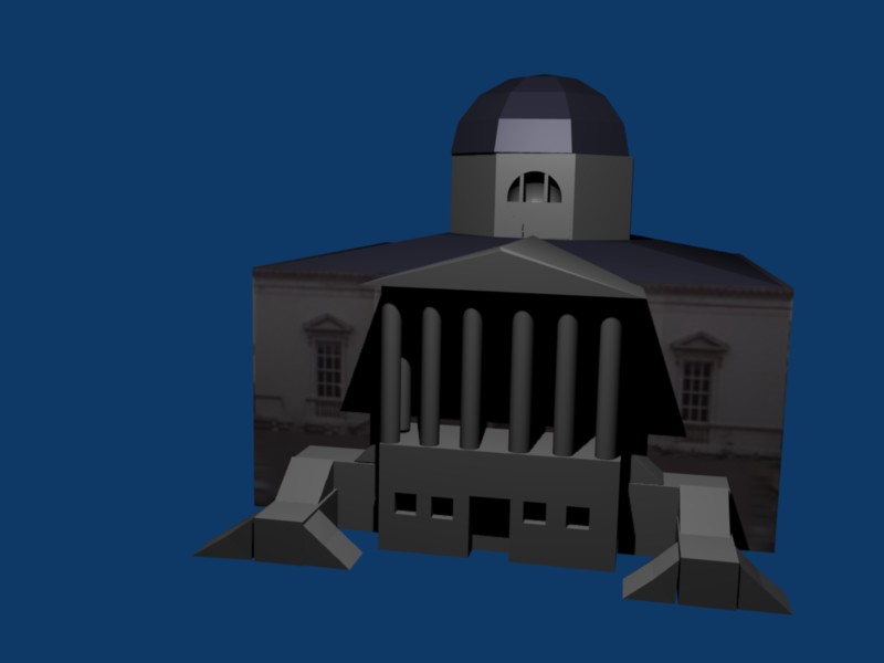
· The portico: adding volumes and editing them o Add the base by adding a cube : to add a volume, press the space bar, and select ‘Add/Mesh/Cube’. Manipulate the cube (manipulator as usual) so that it reaches the proportions shown on the plan, and position it in front of the base of the house, in the middle: to reposition a volume, select it (right click), press G (grab) and pull it with the mouse. o Create the columns with Add/Mesh/Cylinder, scaling and manipulating them, rotating them if necessary, till the proportions are right. To duplicate them, select the first column, and press Shift D simultaneously, then grab the column to see the second column detach itself. Create six columns for the front plus one for each side. View the result. o Create the roof: a cube with the same measurements as the portico, then manipulate it to make it low. Then pass in Edit mode (menu in the header: Object mode serves to modify objects as a whole, Edit mode to change their inner proportions), edit in in 'vertex' mode - button in the header ('vertex' will edit the 'vertices' or end points of the volumes, 'edge' the external lines, 'face' the surfaces); grab the top corners (perspective or camera view will be better to select them- 'View' menu in the header) , towards the centre till they reach the right position. o Create the pediment: add a cube, pass in edit mode, edge mode, select the top side edge, drag it towards the middle, and do the same for the symmetrical one. |
|
|
The dome: selecting with a bounding box, doing boolean operations o create a cylinder with 8 sides (an octagon), manipulate and rotate it to position it in the middle of the roof. o for the cupola, create a sphere (Add/Mesh/Sphere), in edit mode deselect it (A key); to suppress the lower part, place your pointer at the point where the selection should start - at the level of the middle of the sphere, then press B for opening a bounding box (dotted lines) and drag your mouse to select the lower half, then click on 'suppress'; position the top part on the octagon. o For the Diocletian
window, create a small sphere, place it in the front wall of the octagon.
Deselect everything (A key). In Object mode, select first the octagon, then
(press Shift to select several volumes simultaneously) select the small
sphere. Press W then Boolean/Difference: the sphere (selected second) will be
subtracted from the octagon (selected first), leaving a circular opening in
it: drag the now useless sphere apart, and the octagon, you will see the
second octagon with an opening. For the definition of Boolean operations see Complex Outlines. |
|
|
· The flights of steps: create
them with cubes as bases, and for the steps cubes transformed into
triangular sections in edit mode. · Add the stacks on top (lengthened cubes with thinner top in edit mode). |
|
